
Left Image: The clipped plane is rendered with emissive illumination. This removes the random lighting. The colon walls are the same.

|
Right Image: The clipped volume data shows random lighting. The colon walls are lit correctly. Left Image: The clipped plane is rendered with emissive illumination. This removes the random lighting. The colon walls are the same. |
|
We present the emissive clip plane as a pragmatic solution for two illumination problems when cutting through a volume. First, noisy gradients create random lighting; second, back facing surfaces reveal dark areas. Both lighting and clipping are advantageous features of volume rendering, a solution that allows them to be used together is very desirable.
The random lighting comes from illuminating a homogeneous material using an estimated gradient. The gradient is derived from neighboring voxels. VolumePro[1] uses the central difference to estimate gradients, but any algorithm will have the same problem. Since the neighbors are very similar values, but with some noise, the resulting gradients have random orientations. When these gradients are used as the normal in the Phong illumination model[2], the result is also random.
In volume data, the surfaces are implicitly defined by regions with larger gradients. Those surfaces pointing toward lights get brighter. The back facing surfaces will not be lit, but they are still visible as dark regions. We wish to remove the lighting effect at the clip plane surface.
The emissive clip plane solves both of these problems by overriding the lighting parameters immediately adjacent to the clip plane with purely emissive illumination. Emissive is used in the OpenGL[3] sense - the resulting color is the color from classification with no additional modification. We use the term clipping as a general term for any sort of cutting operation that makes the volume transparent on one side. VolumePro1000 has three types of clipping:
Lighting Reveals Shape. |
|
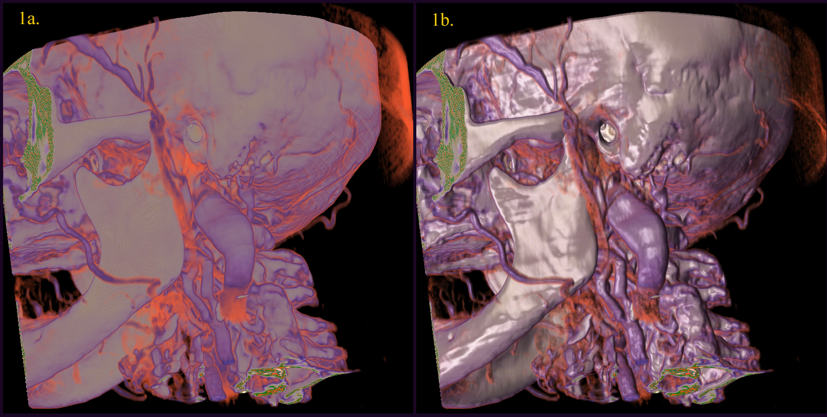 |
Image 1a is not lit, rather it uses emissive illumination. Image 1b is lit with diffuse and specular reflections.
Shading was used by both the early Greeks and Chinese painters to depict 3D shapes in 2D images. Illumination was known to dramatically improve the "realism" of 3D computer graphics [4] very early on. Lighting is also a key feature in volume rendering[5] where we are often more concerned with visualization than with realism. How humans perceive "shape from shading" is an active research topic in cognitive psychology[6][7] and physiology[8]. |
Clipping reveals inner details. |
|
 |
To the left, Image 1c is clipped revealing the interior stucture. Image 1d is both lit and clipped, thus revealing the problem we are solving.
Volume data is most often captured using Computed Tomography (CT) scan, which uses X-Rays to penetrate the surface of objects and measure the density through out an object. Many other modalities create volume data: PET, MRI, Ultrasound. Sampling in three dimensions is the key distinguishing feature of volume data. The internal structures can be shown by adjusting the transfer function (the density to RGBA mapping) used in classification. The surfaces can be shown using the gradient magnitude to modulate opacity and cutting through the volume reveals the inside. |
 |
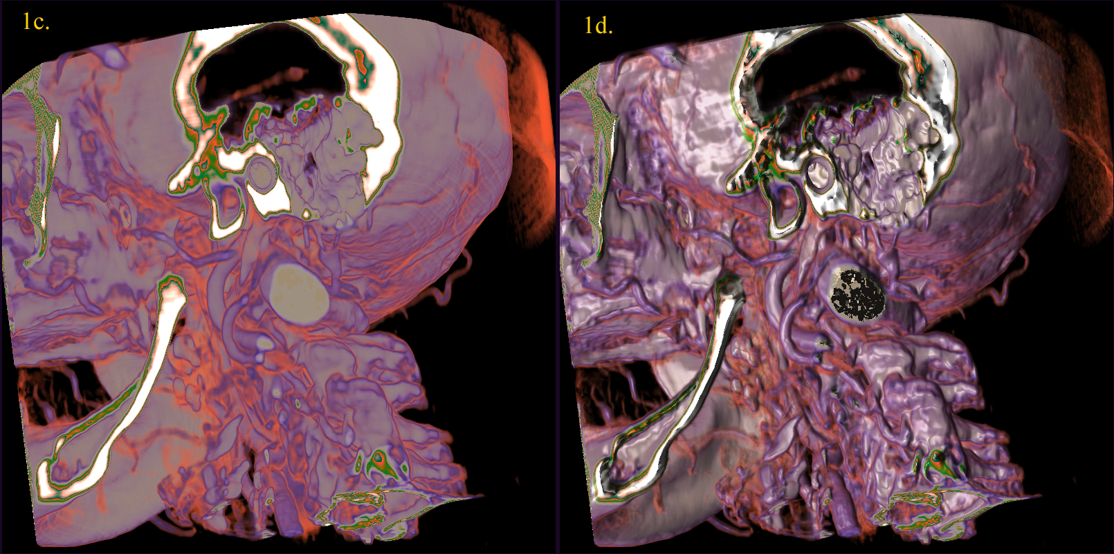
Other Solutions to the Problems of Illuminating Clip PlanesThe first solution we tried was to simply ignore the clipped voxels. While this did a good job with the lighting, it introduced a new problem in the most common case. Samples are created along rays through the volume. These samples are interpolated from neighboring voxels and then rendered. Near the clipped surface we used zero value voxels for the interpolation and as a result, showed incorrect materials. This is illustrated in Image 2c. This would be avoided if we classified (assigned RGBA values based on voxel value) before interpolating and clipping. The VolumePro 1000 implements this, but, it is much more common to interpolate the samples and then classify. In Image 2d. we have used the gradient magnitude to modify the lighting. In this case we have removed the illumination effect of the very smallest gradients. This removes the random lighting of homogeneous materials. In this case the result is too dark. Joe Kniss et al.[9] also articulated the problem of trying to illuminate a homogeneous region of a volume. Their solution is to use the gradient magnitude to interpolate between results of the lighting calculation and the unlit sample. This general solution would give us the correct result for the vein, however, it does not affect the cut through the skull. In this case the gradients a valid and strong. Image 2e. shows the emissive cut plane for this test case. If you click on the image you will see two other renderings (2a, 2b). We have a lit volume in Image 2a. and in Image 2b. it is clipped. There are two parts of the image that are unsatisfactory: the jugular vein near the bottom and the skull above it. The next approach was to modify the gradients near the cut surface. |
| |
|
 |
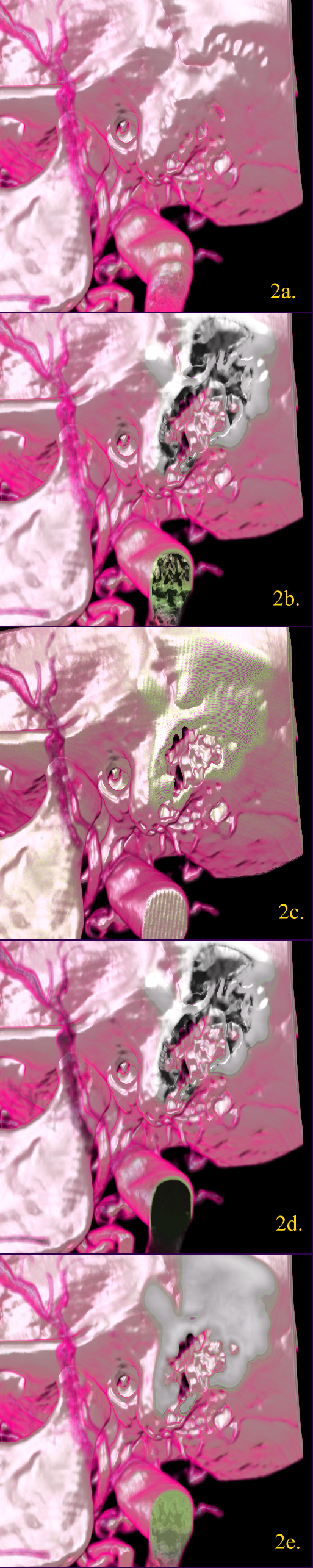
Modifying GradientsThe first image is with no gradient modification. To solve the darkness at the cut surface we tried a number of methods of modifying the gradients. The simplest is just to replace the estimated gradient with the clip plane normal. This is shown in the second image. We see a sharp cut surface but lose the details on surface. We also tried blending the plane normal with the estimated normal. The most promising blend approach was based on decomposing the estimated gradient into two components: one component along the normal of the clipping surface and the other, the tangent is on the surface. The blended normal is composed of the cut plane normal and the tangent component of the estimated gradient. The third image shows cut surface effects while preserving some gradient details on the clipping surface. While modifying the gradient gave us most of what we wanted it is very expensive to do in hardware, especially the decomposing and blending of gradients. However, the strongest reason to reject gradient modification is that customers did not like the specular reflection on the cut plane, but they still wanted it on the volume itself. |
All images were rendered using the TeraRecon VolumePro 1000. The gradient modification images were created by computing the gradient in software to create four field voxels - gradient X, Y, Z and the original sample data. This was rendered using the gradient estimation bypass.
CT dataset of the head, courtesy of Massachusetts General Hospital.
We'd like to thank everyone at TeraRecon, Inc. that helped to find the solution presented here.